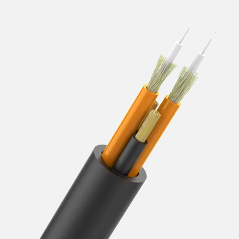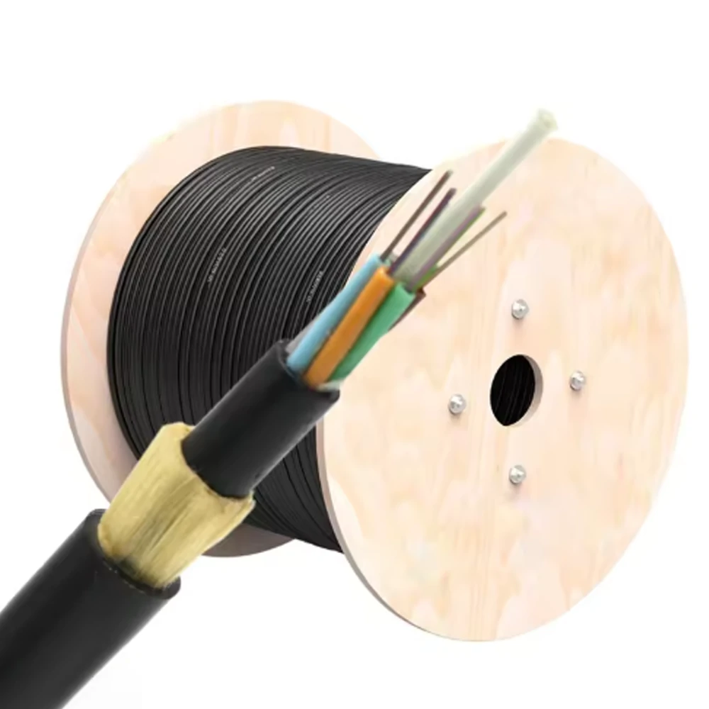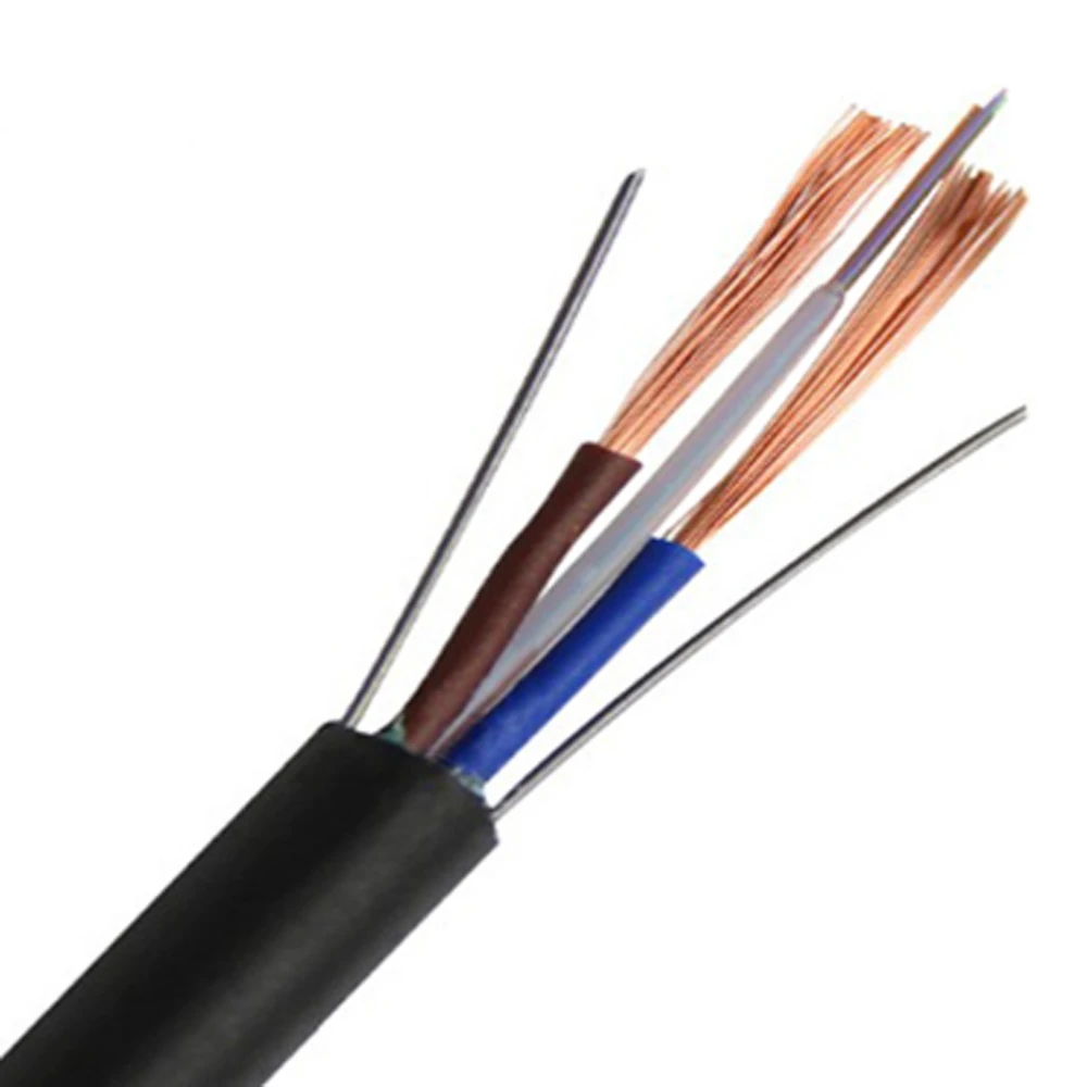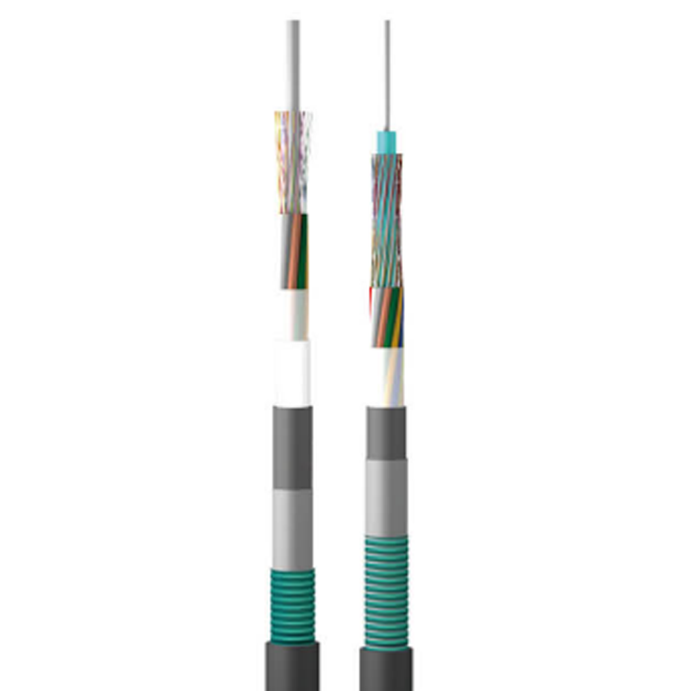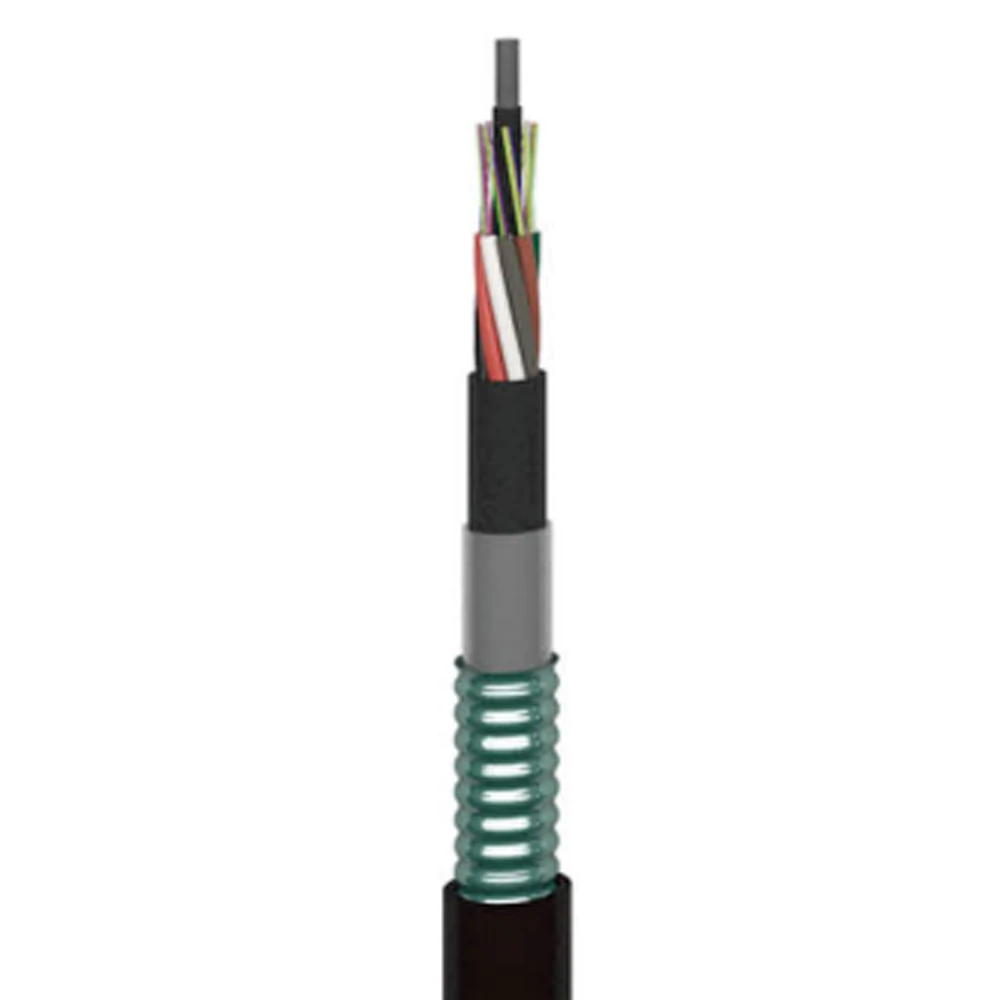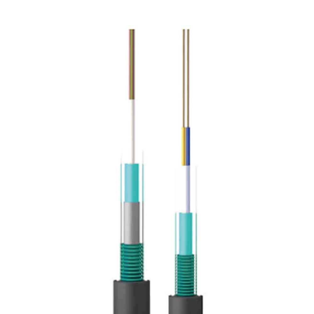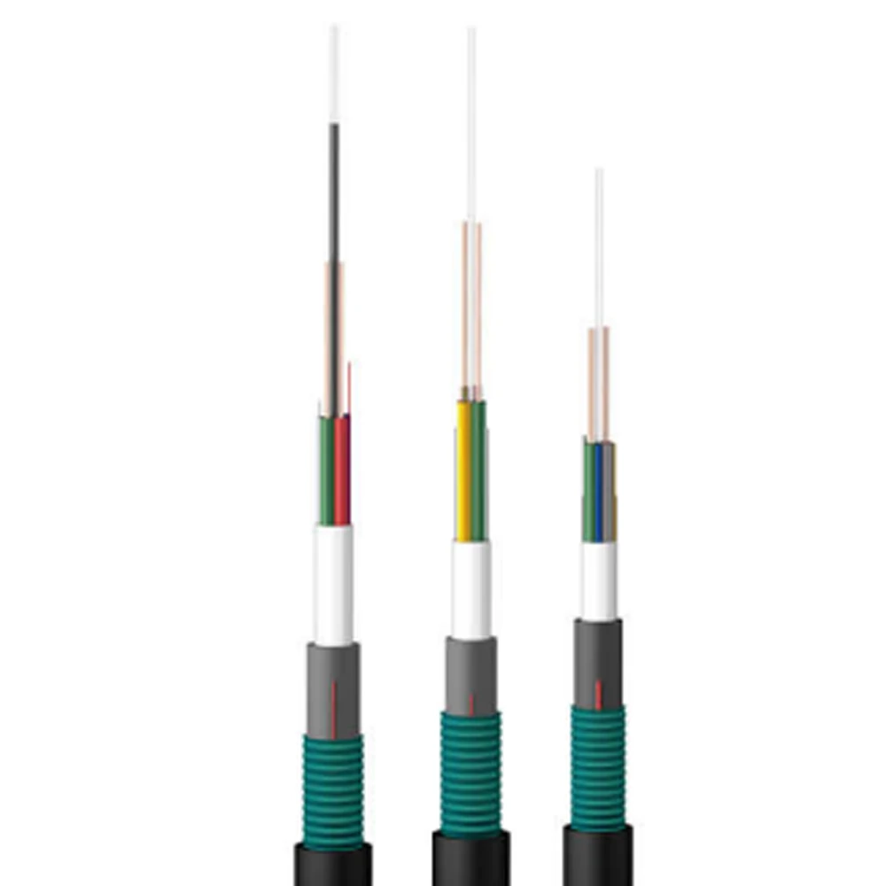





| Product Specification | Reference Outer Diameter (mm) | Reference Weight (kg/km) | Allowed Tensile Load Long-term/Short-term (N) | Allowed Crush Load Long-term/Short-term (N/100mm) | Reference Structure |
| GDTA53-02-24Xn+2×1.5 | 15.1 | 290 | 1000/3000 | 1000/3000 | Type I structure |
| GDTA53-02-24Xn+2×2.5 | 15.5 | 312 | 1000/3000 | 1000/3000 | Type II structure |
| GDTA53-02-24Xn+2×4.0 | 17.8 | 358 | 1000/3000 | 1000/3000 | Type II structure |
| GDTA53-02-24Xn+2×5.0 | 18.6 | 390 | 1000/3000 | 1000/3000 | Type III structure |
| GDTA53-02-24Xn+2×6.0 | 19.9 | 435 | 1000/3000 | 1000/3000 | Type III structure |
| GDTA53-02-24Xn+2×8.0 | 20.8 | 478 | 1000/3000 | 1000/3000 | Type III structure |
| Conductor Cross-section (mm²) | Max. DC Resistance per Conductor (20°C) (Ω/km) |
Insulation Resistance (20°C) (MΩ·km) Between each insulated conductor and other interconnected metals in the cable |
Dielectric Withstand Strength (kV, DC 1 min) | ||
| Between Conductors | Conductor to Metallic Armor Tape | Conductor to Steel Wire | |||
| 1.5 | 13.3 | Not less than 10000 | 5 | 5 | 3 |
| 2.5 | 7.98 | ||||
| 4.0 | 4.95 | ||||
| 5.0 | 3.88 | ||||
| 6.0 | 3.30 | ||||
| 8.0 | 2.47 | ||||
Note: Specifications shown are standard values. Actual performance may vary depending on installation environment, component compatibility, and grid conditions. We reserve the right to continuously optimize design and specifications. For final technical proposals and formal quotations, please contact our sales team to request an official specification confirmation document.